VLAN in a small network
Suppose that you have a small network that consists of the following components:
- Number of servers
- VoIP phones
- Number of clients
- A single router
- One or two switches (we'll assume only one switch here, though there might be more than one)
The possible reasons why you would like to segment your network are:
- VoIP traffic is not encrypted and by separating it you achieve a certain level of security (not absolute though!).
- VoIP traffic is sensitive to delay and loss so by isolating it you could achieve better quality
- By separating servers and placing firewall/router between servers and clients you can better control who can access what.
The following figure is a visualisation of a topology we are trying to achieve. There are three VLANs, one for servers (VLAN ID 1), another one for VoIP phones (VLAN ID 2) and one for workstations (VLAN ID 3). The router is connected to all VLANs and it is used for routing and firewalling purposes.
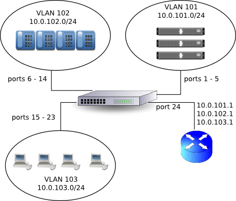
The configuration examples on this page are for Linux and HP ProCurve 2524 switch.
Configuring switch
We'll start by configuring switch. Assumption is that the switch has only basic configuration done, i.e. passwords are set, IP address is assigned, and hardening was performed.
Log to switch as manager and enter configuration mode:
HP ProCurve Switch 2524# conf t
HP ProCurve Switch 2524(config)#
Configure VLAN 3:
HP ProCurve Switch 2524# vlan 103
HP ProCurve Switch 2524(vlan-103)# name Clients
HP ProCurve Switch 2524(vlan-103)# untagged 15-23
HP ProCurve Switch 2524(vlan-103)# tagged 24
HP ProCurve Switch 2524(vlan-103)# exit
HP ProCurve Switch 2524#
This set of commands sets the name of VLAN to Clients, adds ports 7 to 12 as untagged and port 24 as tagged to the VLAN. Untagged means that the Ethernet frames that enter the switch don't have VLAN tag in them so that the switch has to add the tag itself if necessary. Tagged on the other hand means that the Ethernet frame that enters the switch will have VLAN tag embedded into it. The port 24 will be used to connect firewall and we'll configure it to add VLAN tag by itself.
Next, configure VLAN 2:
HP ProCurve Switch 2524# vlan 102
HP ProCurve Switch 2524(vlan-102)# name Phones
HP ProCurve Switch 2524(vlan-102)# untagged 6-14
HP ProCurve Switch 2524(vlan-102)# tagged 24
HP ProCurve Switch 2524(vlan-102)# exit
HP ProCurve Switch 2524#
And finally, configure VLAN 1 for servers:
HP ProCurve Switch 2524# vlan 101
HP ProCurve Switch 2524(vlan-101)# name Servers
HP ProCurve Switch 2524(vlan-101)# untagged 1-5
HP ProCurve Switch 2524(vlan-101)# tagged 24
HP ProCurve Switch 2524(vlan-101)# exit
HP ProCurve Switch 2524#
Write configuration to flash and exit from switch:
HP ProCurve Switch 2524# write memory
HP ProCurve Switch 2524# exit
Configuring firewall
Now we need to configure firewall. The assumption, as shown in the Figure, is that the firewall is connected with a single Ethernet interface to a switch. On this Ethernet interface we'll configure three VLANs:
# vconfig add eth0 101
# vconfig add eth0 102
# vconfig add eth0 103
# ip link set dev eth0.101 name vlan101
# ip link set dev eth0.102 name vlan102
# ip link set dev eth0.103 name vlan103
# ip link set dev vlan101 up
# ip link set dev vlan102 up
# ip link set dev vlan103 up
# ip addr add 10.0.101.1/24 dev vlan101
# ip addr add 10.0.102.2/24 dev vlan102
# ip addr add 10.0.103.3/24 dev vlan103
# echo 1 > /proc/sys/net/ipv4/ip_forward
The vconfig commands create VLAN interfaces in kernel. The interfaces are by default named something like eth0.101@eth0 even tough they are manipulated by using only the part before at sign. The ip link set ... name ... commands are used to change names into something easier to remember. Then, interfaces are activated with ip link set ... up commands. The ip addr ... commands are used to set IP addresses to the VLAN interfaces. Finally, echo command enables routing in the kernel.
This is enough for connectivity to be established between networks. The next step would be to configure firewall rules.
Troubleshooting
In case something goes wrong tcpdump is your friend, as usual. Note that using tcpdump on vlan? interfaces will show you Ethernet frames without VLAN tag, while if you use tcpdump on eth0 interface you'll see VLAN tag. For example:
# tcpdump -enni eth0
17:53:09.363802 00:e0:4d:bc:ad:a3 > 00:1e:58:fa:db:1f, ethertype 802.1Q (0x8100), length 102: vlan 102, p 0, ethertype IPv4, 10.0.102.2 > 10.0.103.2: ICMP echo reply, id 54273, seq 101, length 64
17:53:09.363834 00:1e:58:fa:db:1f, > 00:e0:4d:bc:ad:a3, ethertype 802.1Q (0x8100), length 102: vlan 103, p 0, ethertype IPv4, 10.0.103.2 > 10.0.102.2: ICMP echo reply, id 54273, seq 101, length 64